Lionel Weicker
Senior Data Scientist Expert
Generate an interactive 360° view of an object

360 degrees views are increasingly popular nowadays, utilized to create panoramic photos or virtual reality experiences just by rotating the device around while holding the position fixed.
In this article, we propose a different approach which consists in capturing a video while moving around a fixed object. As an example, for this blogpost, we consider rotating around a person, but the same process can be applied to any object.
To be more precise, the objective is to create a centered, stabilized, and interactive 360° view of the person using minimal device equipment, i.e. just a smartphone to capture the video and a computer to process it.
We describe hereafter our approach to this challenge, what issues have been encountered and how they have been dealt with.
Workflow
Here is the workflow we followed to reach the objective:
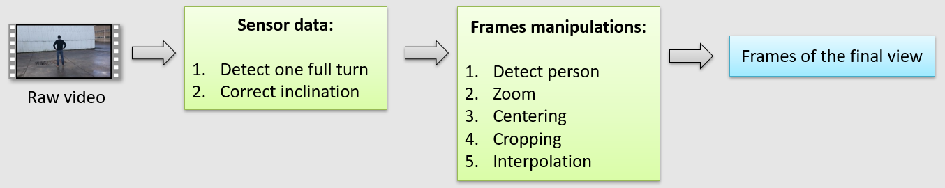
It is decomposed in three parts:
- create a mobile application to record a video with sensor data associated to each frame
- use the sensor data to:
- detect when one full rotation around the person has been completed
- adjust the inclination/tilt of each frame
- process each frame of the video. Specifically, we sequentially:
- locate the person on each frame using deeplearning techniques
- apply a zoom to have same person height, then center the frame on the person
- crop each image to remove unnecessary parts of the original frame
- interpolate frames to have a better user experience when interacting with the 360° view.
Mobile Application
We developed a mobile application for Android to capture videos and collect sensor data associated to each frame.
Different sensor data are available on modern smartphones. For the purpose of this project, we only take advantage of the magnetometer and accelerometer sensors. Those sensors have data following the 3 axes represented in the following figure:
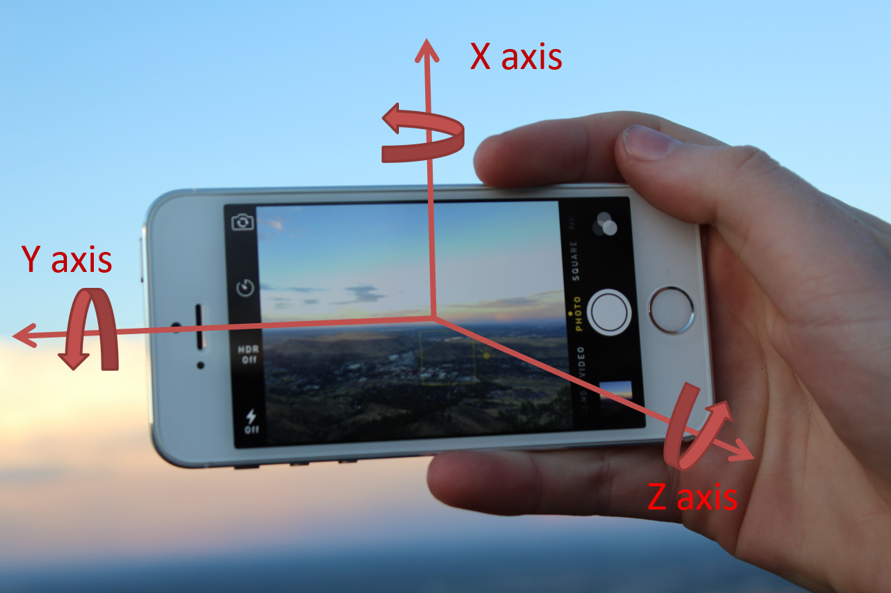
The values of the three angles can be retrieved using Android SDK. For the following, we only take advantage of two axes:
-
X-axis, which corresponds to the relative position of the person who captures the video: it is used to know when a full rotation around the person being filmed is completed
-
Z-axis, which represents the inclination of the smartphone with respect to the horizontal axis: it is used to correct the inclination of each frame.
Here is an example of video taken with our Android App:
This video is composed of approximately 1250 frames. The sensor data associated to each frame are included in the video as metadata and are called ‘Acceleration’ and ‘Attitude’ for x- and z-axis, respectively ( Video metadata can be accessed using some tools like exiftool )
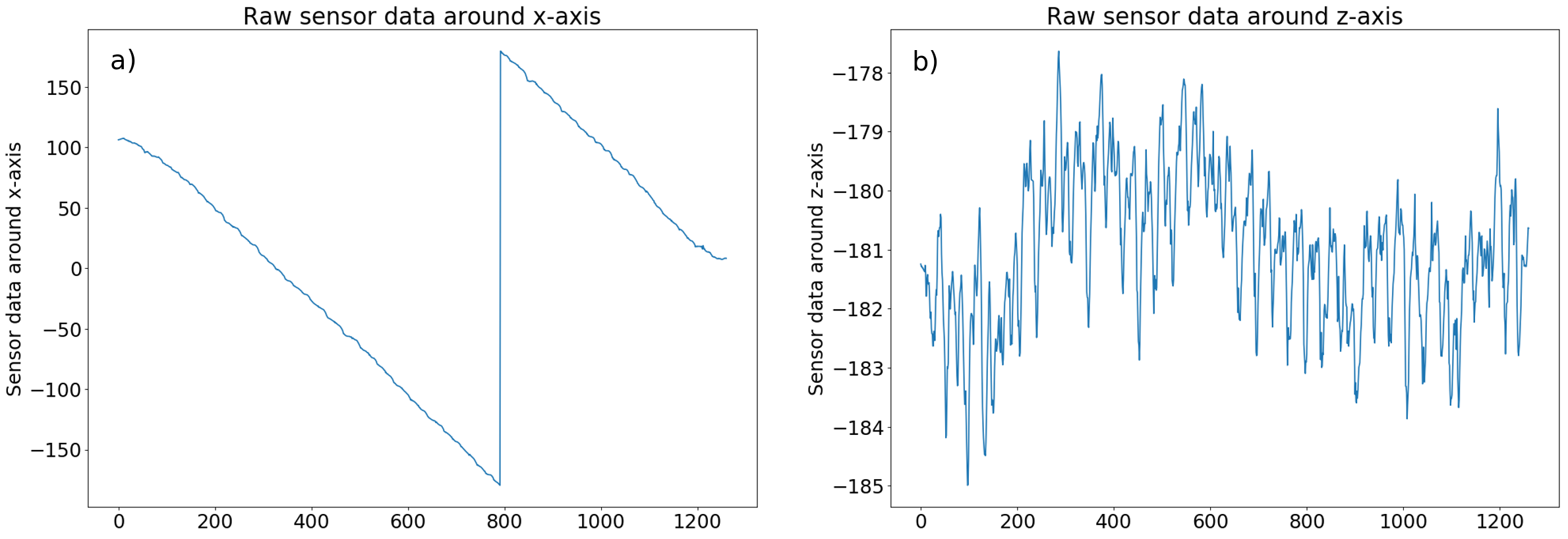
Figure a) represents the sensor data recorded for the X-axis as function of the frame ID of the video. Overall, the sensor data for the X-axis vary between -180° and +180°, which is the expected result since the data correspond to the relative position around the fixed person. An absolute variation of 360° corresponds to a full rotation. Note that if we captured the video by rotating around the person in the other direction, we would have observed increasing curves instead of decreasing ones. Finally, we observe that small noises are present because of inevitable oscillations of the person holding the device.
Figure b) shows the sensor data recorded for the Z-axis as function of the frame ID of the video. We observe noisy data oscillating around -181°. The perfect case would have been -180° for Z-axis value at each frame, i.e. no variation of the inclination of the smartphone.
Now that we have sensor data and an understanding of them, we can apply transformations to the video.
Video transformations
Transformations using sensor data
X-axis
The transformations of the X-axis sensor data are represented in the figures b) and c) whereas a) corresponds to raw data:
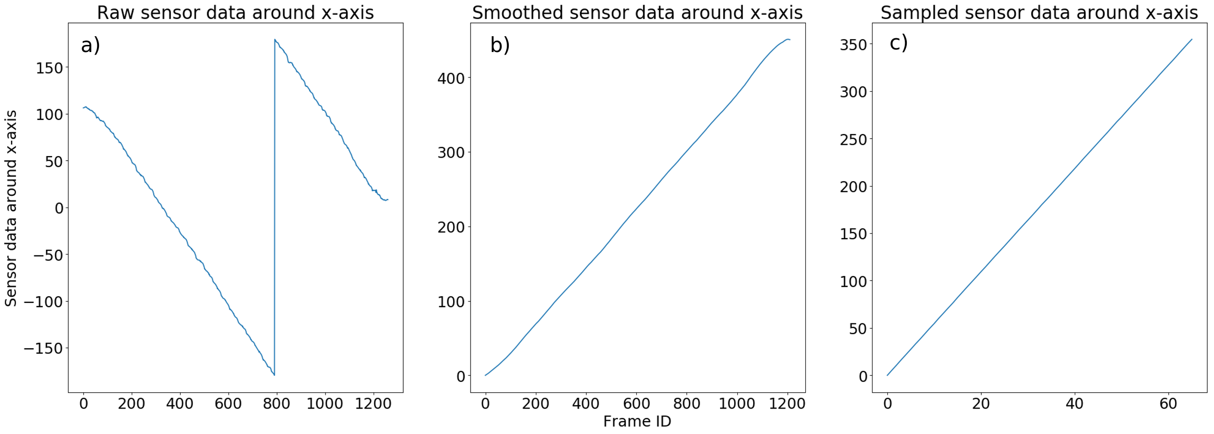
Firstly, we need to modify the sensor data to only have increasing variation of the angle starting from 0 to facilitate the next transformation and avoid dealing with discontinued data.
Secondly, we observe that the data in Figure a) are subject to noise due to sensors being not perfect and coming with errors in precision. To smooth/remove undesirable noises, we apply a moving average. After some tests, we observed that a good compromise is obtained with a moving average over 30 frames. The results of the first and second process are shown in Figure b).
Additionally, we want to know at which frame ID a full rotation around the person is completed: to do that, we only keep frames which have an angle between 0° and 360°, which approximately corresponds to frame ID between 0 and 1000 on Figure b).
Finally, we sample the frames between 0° and 360° uniformly, to reduce the process time of the next steps and to have a smoother 360° view experience. To this end, we keep 66 frames in a 360 degrees range.
The result of this process is represented in Figure c). We note that we obtain almost a perfect straight line. For the following, we only consider 66 frames.
Z-axis
The process for the z-axis is similar to the one for the X-axis. The results are represented in the following figures:
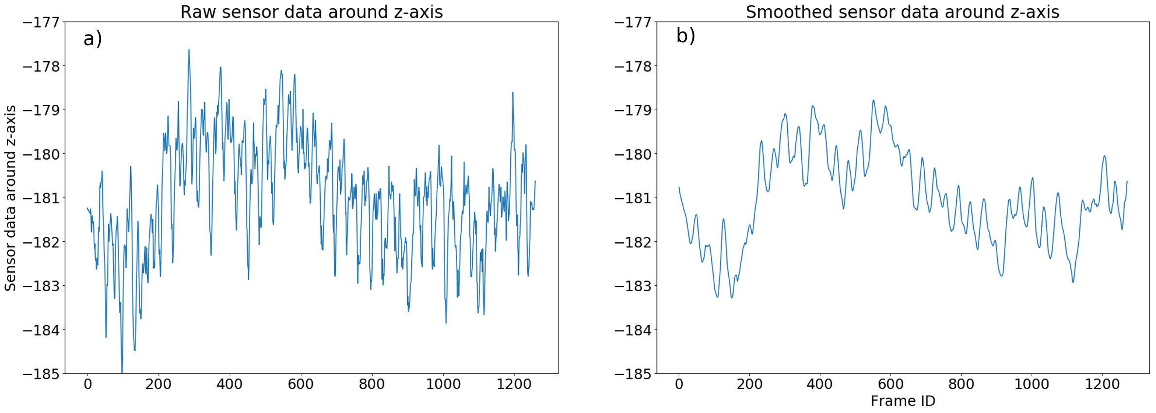
Similarly to the X-axis data process, we smooth the sensor data around Z-axis to reduce noise with a moving average over 10 points (see Figure b)) followed by the same sampling used during the X-axis transformations.
Using the smoothed and sampled sensor data around Z-axis, we now correct the inclination of each frame to make it perfectly horizontal, i.e. have a Z-axis value of -180°. With this transformation, we expect to reduce titling of the person being captured. An example of this process is represented in the following figure:
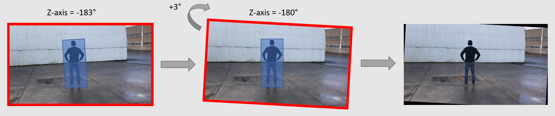
The blue box corresponds to the person being captured. The first picture on the left shows the frame we want to correct. The Z-axis sensor data associated to this frame is -183°: we want to have a final frame having a Z-axis value of -180°. We therefore apply a rotation of 3° (see figure in the middle). Since the frame must have vertical and horizontal boundaries, we finally crop the middle frame keeping the same resolution as the original image, which leads to a new frame (picture on the right) that will be used for the next step. Note that the resulting picture of this process leads to black areas, this problem will be solved in the next section. The remaining 65 frames are processed the same way.
The result of this process is represented in the following video:
Transformations using deeplearning and image transformation techniques
We want each frame to have the person at its center and at the same height between each frame. To do that, we need to know the person’s position on each of the 66 frames obtained from the previous transformations. To save time, we evaluated deep learning pre-trained models such as RetinaNet for object detection. The results using this model are shown in the following pictures:
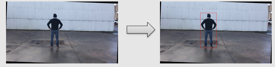
The detection is applied to the 66 frames of the previous transformations and leads to the following result:
Once the bounding boxes positions and sizes are computed for each frame, we use these data to adjust the zoom levels between 2 consecutive frames to have about the same box height between them.
Following the detection process, we adjust zoom levels and center each frame based on the bounding box dimensions derived from the detection results. We then remove black areas obtained during the rotation of the pictures and have the same resolution for each frame. We fixed a ratio width/height of the cropped image to be 1/2. The result of this process is shown in the following video:
The person is now centered. Unfortunately, we still have shaky transitions between each frame. To smooth the transition between frames while interacting with the 360° view, we use motion interpolation techniques, generating additional frames to create a smoother interaction. For this blogpost, we decided to generate 2 frames between 2 real frames leading to a total of 133 generated frames for 66 real frames.
The result of this process is shown in the following video:
Note that, when seeing the results at a constant speed like this, we feel like the quality hasn’t improved. This will be optimized further with a smart viewer in the next section.
WebViewer
As a basis, we use this WebViewer, which has been modified to only stop on real frames when interacting with the 360° view. Generated frames are only displayed when moving the cursor.
The final interactive 360° view is the following:
You can interact with the WebViewer by clicking on the picture and drag to the left or to the right with your mouse. If WebViewer is not displayed, you can access it using this link.
Conclusion
In this article, we presented the process of creating an interactive 360° view of a person, the challenges encountered and how we approached them. We have seen that the subject is not limited to Computer Vision and actually spans many areas suchs as artificial intelligence, statistics, video recording, capture sensor data, transformation of frames in video,…
This technique can be applied to different domains such as making 360° views around other objects like clothes, shoes, car, furniture’s, food, to allow the user to check the product on every angle.